
Measuring the length of externally threaded fasteners—such as bolts, screws, and studs—may appear straightforward. In practice, however, different standards define length in different ways. If these rules are not clearly distinguished, disputes may arise during inspection, assembly, or export acceptance.
This document is based on GB/T 3106-2016 Nominal Lengths and Thread Lengths of Bolts, Screws and Studs (equivalent to ISO 888), as well as ASME standards (B18.6.3-2024, B18.2.1-2012 R2021). It systematically explains the measurement logic, highlights key differences between standards, and provides practical guidance for real-world applications.
1. Length Measurement Rules under GB / ISO Standards
Under GB/T 3106-2016 (ISO 888), the core principle is “measurement from the actual bearing surface, with the measurement taken strictly parallel to the fastener axis. The starting point varies depending on the astener type.
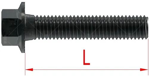
1.1 Fasteners with Flat Bearing Surfaces
(Hex head, hex flange head, pan head, round head, large flat head, socket head, etc.)
For bolts and screws whose head bearing surface lies in a single plane, the nominal length is measured from the head bearing surface to the end of the shank.
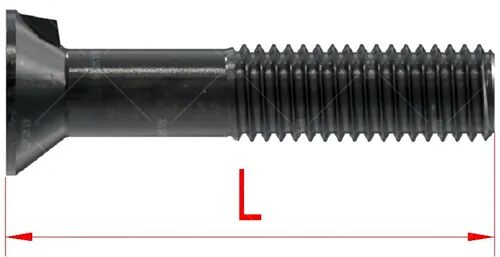
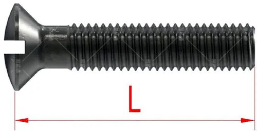
1.2 Countersunk and Raised Countersunk Heads
For countersunk or raised countersunk fasteners, the nominal length L is defined as the distance from the theoretical intersection line between the head top surface and the head diameter to the end of the threaded portion.
1.3 Headless Screws and Set Screws
For headless screws and set screws, the length is measured from one end of the screw to the other end.
1.4 Studs
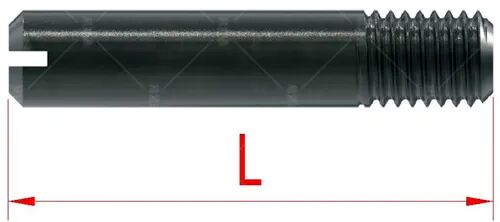
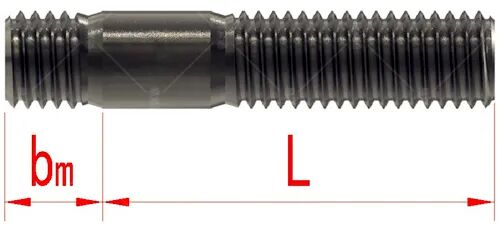
1.4.1 Partially Threaded Studs (Unequal Double-End Studs)
The length is measured from the thread run-out at the end intended for insertion into the base material to the free end of the nut side.
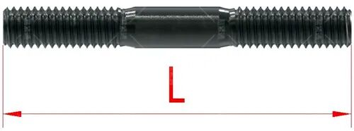
1.4.2 Equal Double-End Studs, Tie Rods, Single-End Studs, Fully Threaded Studs (Threaded Rods)
For equal-length double-end studs, tie rods (including left-hand/right-hand threaded studs), single-end studs, and fully threaded studs, the nominal length is measured from one end of the stud to the other.
2. Length Measurement Rules under ASME Standards
According to ASME standards such as ASME B18.6.3-2024 and ASME B18.2.1-2012 R2021, the definition of fastener length is generally similar to that of GB/ISO.
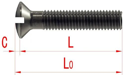
However, for countersunk and raised countersunk fasteners, ASME additionally defines:
- Nominal length (L)
- Head height or crown height (C)
- Overall length (L₀), measured from the top of the head to the end of the shank
These additional dimensions are critical for acceptance in the North American market.
3. Provisions on Thread Length (b)
In addition to nominal length L, thread length b is a key dimensional parameter.
3.1 Thread Length under GB / ISO Standards
Unless otherwise specified in the product standard, the thread length b is determined as follows:
| Nominal Length L (mm) | Thread Length b (mm) |
|---|---|
| L ≤ 125 | 2d + 6 |
| 125 < L ≤ 200 | 2d + 12 |
| L > 200 | 2d + 25 |
If the unthreaded shank length is ≤ 0.5d, the fastener shall be fully threaded.
3.2 Thread Length under ASME Standards
3.2.1 Measurement Method
According to ASME B18.6.3-2024, thread length for machine screws is measured along the axis, starting from the bearing surface under the head and ending at the point where a Class 3A GO thread ring gauge (without counterbore or chamfer) stops when screwed on by hand.
3.2.2 Thread Length Requirements
| Thread Size (d) | Nominal Length (L) | Max. Unthreaded Length Under Head | Thread Length |
|---|---|---|---|
| d ≤ No.5 | L ≤ 3d | ≤ 1P | Fully threaded |
| d ≤ No.5 | 3d < L ≤ 1-1/8 | ≤ 2P | Fully threaded |
| d ≤ No.5 | L > 1-1/8 | ≤ 2P | ≥ 1 |
| d ≥ No.6 | L ≤ 3d | ≤ 1P | Fully threaded |
| d ≥ No.6 | 3d < L ≤ 2 | ≤ 2P | Fully threaded |
| d ≥ No.6 | L > 2 | ≤ 2P | ≥ 1 |
Units: inches. “P” denotes thread pitch.
4. Practical Considerations in Measurement
4.1 Application-Oriented Standard Selection
For domestic projects, GB/ISO standards are generally applied.
For exports to North America, ASME standards must be strictly followed.
For example, countersunk screws exported to the U.S. should clearly specify nominal length (L), head height (C), and overall length (L₀) to avoid inspection disputes.
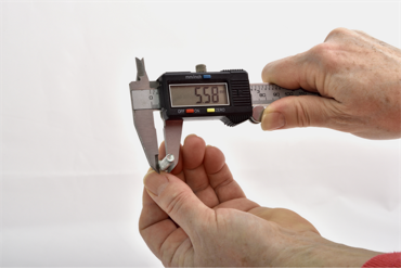
4.2 Selection of Measuring Tools
Measuring tools should be selected based on the required accuracy:
- Vernier calipers (resolution ≥ 0.02 mm) for general applications
- Thread ring gauges, micrometers, and other dedicated gauges for high-precision requirements
When measuring countersunk screws, ensure the tool is perfectly aligned with the fastener axis to avoid positional errors at the theoretical head intersection line.
4.3 Priority of Product-Specific Requirements
The rules described above represent general provisions in common standards.
If the product drawing, specific product standard, or technical specification defines special requirements, those requirements shall take precedence over general standards.
5. Common Measurement Errors
Error 3: Mistaking the ASME-defined overall length (L₀) of a raised countersunk screw for the nominal length (L).
Error 1: Measuring a hex bolt from the top of the head instead of the bearing surface, resulting in an overestimated length (approximately equal to head thickness).
Error 2: Treating the total length (bm + L) of an unequal double-end stud as the nominal length L.


